Every slope has a breaking point, and I’ve stood on enough failed hillsides in the Front Range to know that a single oversized wall is often the wrong answer to a steep grade. Tiered retaining wall design solves a real engineering problem: how to hold back significant elevation change without building one massive structure that concentrates enormous soil pressure on a single footing. Done correctly, a stepped retaining wall system distributes load, simplifies drainage, and often keeps each individual tier below the height threshold that triggers a full engineering review. Done poorly, it becomes a stack of independent walls that nobody analyzed as a whole system – and that’s when terraced slopes start to slide. This article walks through the setback rules, the global stability concept most homeowner guides skip entirely, and how a licensed engineer actually sizes a multi-tier wall system for Colorado terrain. Learn more about when a retaining wall needs an engineer.
Table of Contents Learn more about Drone Inspection.
Why Tiered Walls Instead of One Tall Wall?
Tiered walls break a tall slope into a series of shorter walls rather than one continuous structure, and the main reason is load reduction. Lateral soil pressure increases roughly with the square of wall height, so a 12-foot wall doesn’t carry twice the pressure of a 6-foot wall – it carries roughly four times the pressure at its base. Splitting that same 12 feet of elevation change into two 5- to 6-foot tiers dramatically cuts the overturning and sliding forces each individual wall has to resist.
There’s also a practical permitting angle. In most Colorado jurisdictions, including Denver, Boulder, and Colorado Springs, walls exceeding 4 feet in height measured from the bottom of the footing to the top of the wall require a stamped engineering design, per IBC Section 1807 and local amendments. A well-designed tiered retaining wall can sometimes keep each tier under that 4-foot threshold – though, as I’ll get into shortly, that doesn’t mean the whole system escapes engineering scrutiny.
What Practical Advantages Do Terraced Retaining Walls Offer?
Terraced retaining walls offer three concrete advantages over a single tall wall: reduced per-tier loading, simplified construction logistics, and improved drainage staging. Each tier can be built with lighter materials, shallower embedment, and smaller equipment than a monolithic wall of equivalent total height.
- Lower lateral earth pressure per tier reduces the required footing width and reinforcement steel, often cutting concrete volume by 20-30% compared to an equivalent single wall.
- Shorter walls allow gravity block or segmental systems to be used without geogrid reinforcement in many cases, versus a tall wall that almost always needs geogrid.
- Drainage can be captured and diverted at each level rather than relying on one deep drain system fighting the full hydrostatic head of a 12-foot backfill.
- Planting terraces between tiers create usable landscape space – a real benefit on tight residential lots common in Golden, Lakewood, and Evergreen.
- Construction access is easier on a series of 4-foot lifts than excavating and shoring a single 10- to 14-foot cut.
I’ve designed tiered systems specifically because a client’s lot in Genesee had a 14-foot grade change between the house pad and the rear property line. A single wall would have needed a substantial tieback or geogrid system extending 10+ feet into the hillside. Three stepped tiers of roughly 4.5 feet each solved the same problem with standard segmental block and far less excavation.
What Is the Setback Rule Between Tiers?
The setback rule states that each upper tier must be positioned far enough back from the wall below it that its own weight and the soil wedge behind it don’t add surcharge load onto the lower wall’s reinforced zone. This is the single most misunderstood part of tiered retaining wall design, and it’s the concept most terraced-garden articles never mention because it isn’t visible in a finished photo.
The general industry guideline, drawn from the NCMA (National Concrete Masonry Association) Segmental Retaining Wall design manual, is that the horizontal setback between the face of a lower wall and the face of the wall above it should equal at least twice the height of the lower wall – commonly expressed as a 2H:1 offset – before the upper wall can be treated as structurally independent of the one below it. If the setback is less than that, the upper tier’s soil pressure zone overlaps the lower tier’s reinforced soil mass, and the lower wall must be designed to carry that additional surcharge.
How Is Stacked Wall Setback Calculated in Practice?
Stacked wall setback is calculated by drawing a line at roughly 1V:2H (or using a project-specific angle based on the soil’s internal friction angle) upward from the back-bottom heel of the lower wall’s reinforced zone, and confirming the toe of the upper wall sits behind that line. If it doesn’t, the lower wall’s design must include the upper wall’s weight, live loads, and any surcharge as an added lateral force.
For a lower tier 4 feet tall, that typically means a minimum of 8 feet of horizontal setback before the upper tier can be considered independent – though the actual required distance shifts with the soil’s friction angle, the reinforced soil zone length, and whether geogrid is used. Sandy, low-cohesion soils common in parts of Colorado Springs may need more setback than the stiffer clay-influenced soils found closer to Denver’s older neighborhoods. This is exactly the kind of site-specific variable that makes a generic “rule of thumb” risky to apply without a geotechnical evaluation. Anyone planning multiple tiers on building on a sloped lot should treat the setback calculation as a starting design input, not an afterthought added after the walls are already staked out.
Why Can Global Stability Still Fail Even With Correctly Built Tiers?
Global stability can fail in a tiered wall system even when every individual tier is built to spec, because the failure surface doesn’t respect wall boundaries – it can slip through the soil mass beneath and behind all the tiers simultaneously. This is the difference between a wall failing locally (bulging, cracking, or toppling) and an entire hillside slumping along a deep slip plane that runs underneath the whole terraced slope.
Global stability analysis uses limit-equilibrium methods (Bishop, Janbu, or software like Slide2/GeoStudio) to check dozens of potential failure arcs through the combined soil and wall mass, targeting a minimum factor of safety typically around 1.3 to 1.5 depending on the governing code and risk category. A tiered wall system with three 5-foot walls stacked at minimum setback can still show a global factor of safety below 1.3 if the underlying soil has a weak layer, elevated groundwater, or insufficient overall slope angle – even though each individual wall passes its own sliding and overturning checks.
Tiered systems are engineered as a stack: each tier needs its own design, and closely spaced tiers are often reviewed as one combined structure. ISTA Engineers’ retaining wall design services cover multi-tier layouts from the site visit to permit-ready drawings.
What Are the Most Common Reasons Tiered Wall Systems Fail?
Tiered wall systems most often fail from insufficient setback between tiers, drainage that wasn’t coordinated across the full slope, and a design approach that engineered each wall in isolation rather than as one interconnected system. These three issues account for the majority of tiered wall failures I’ve been called to inspect after the fact.
- Insufficient setback: upper tiers positioned too close to the wall below, silently loading the lower wall’s reinforced soil zone with surcharge it was never designed to carry.
- Uncoordinated drainage: each tier’s drain outlets to the tier below instead of to a collector system, saturating the lower walls and spiking hydrostatic pressure well beyond design assumptions.
- Isolated-wall thinking: a contractor or designer calculates each tier’s sliding and overturning safety factor independently, never running a global stability check through the combined slope.
- Missing geogrid continuity: reinforcement in an upper tier terminates right at the setback line instead of extending far enough to tie into stable soil beyond the lower wall’s influence zone.
- Surface water concentration: roof downspouts, patios, or irrigation systems directing water onto the terraced slope faster than the tiered drainage was designed to handle.
I inspected a four-tier segmental system in Castle Rock two years after construction where the bottom wall had bulged nearly 3 inches at mid-height. Every tier had passed its individual sliding calculation on paper. What nobody had checked was the combined weight of four tiers of saturated backfill sitting on a thin layer of expansive clay about 6 feet below grade – a global stability problem, not a local one. That’s precisely the failure mode retaining wall drainage planning is meant to prevent when it’s designed for the whole slope rather than wall by wall.
How Do Engineers Design a Tiered Retaining Wall System?
Engineers design a tiered retaining wall system by first modeling the entire slope profile as one continuous problem, then sizing each tier’s footing, reinforcement, and drainage based on both its local loading and its contribution to the overall slope’s global stability. The process starts with a geotechnical report – soil boring logs, friction angle, unit weight, groundwater depth – because none of the setback math means anything without real soil data specific to the site.
From there, the design sequence typically runs through slope geometry, individual tier sizing, surcharge verification between tiers, a full global stability run, and a unified drainage plan tying every tier’s perforated pipe into a single outlet system rather than letting water cascade downhill through each terrace. This is meaningfully different from the way retaining wall contractors often approach terraced installs, where each wall gets built to a generic block-manufacturer spec sheet without a project-specific global check.
What Design Steps Does a Structural Engineer Follow for Multiple Tiers?
A structural engineer follows a defined sequence for multi-tier design: site and soil investigation, slope and setback geometry, per-tier lateral pressure and reinforcement sizing, surcharge transfer verification between adjacent tiers, a global stability run across the full slope, and a coordinated drainage layout before finalizing construction documents. Skipping any one of these steps is how “engineered-looking” walls still end up failing five or ten years later.
- Pull soil parameters from a geotechnical report or, at minimum, reasonable regional defaults verified by test pits.
- Lay out tier heights and setbacks to satisfy the 2H:1 (or site-specific) independence rule between each level.
- Size each tier’s footing width, embedment depth, and geogrid layout (if segmental) for its own lateral pressure plus any surcharge from tiers above.
- Run a global slope stability analysis through the full soil-and-wall mass, targeting a factor of safety of at least 1.3-1.5.
- Design a unified subsurface drainage system with collector pipe tying every tier into one or two discharge points, sized per expected stormwater volume.
- Document surcharge loads from anything sitting atop the upper tiers – driveways, patios, structures – since these add real load the lower walls must resist.
This kind of full-system approach is exactly what’s covered under our broader retaining wall design process, and it’s worth checking early whether your project even needs this level of analysis – our page on when a retaining wall needs an engineer breaks down the height and load thresholds that trigger a mandatory stamped design in most Colorado counties.
Which Wall Materials Work Best for Terraced Retaining Wall Systems?
Segmental concrete block, poured concrete, and gabion systems are the three materials most commonly used across tiered retaining wall designs, and the right choice depends on tier height, soil type, and aesthetic goals rather than a one-size-fits-all answer. Mixing materials across tiers on the same slope is common and often practical – a taller lower tier in reinforced concrete with lighter segmental block above it, for example.
| Wall Type | Typical Max Height per Tier | Best Use in Tiered Systems | Relative Cost per Sq. Ft. |
|---|---|---|---|
| Segmental (SRW) block | 4-6 ft without geogrid | Upper, lighter-load tiers; residential terracing | $20-$35 |
| Reinforced concrete | 6-12 ft per tier | Lower tiers carrying the most cumulative load | $35-$55 |
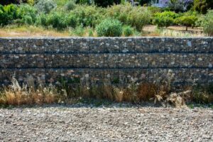
| Gabion retaining wall | 4-8 ft per tier | Steep, rocky sites needing built-in drainage | $25-$40 |
| Timber/landscape | 3-4 ft per tier | Low-load garden terracing only, not slope stabilization | $15-$25 |
For most Front Range residential projects with three or more tiers, I lean toward reinforced concrete retaining wall design for the bottom tier, where cumulative loading is highest, and segmental block above where loads have already dropped off substantially. A segmental retaining wall design on the lower tier is only appropriate when soil conditions and geogrid embedment length can be fully verified through the setback calculation described earlier.
My Experience with Tiered Retaining Wall Design
Over the years I’ve inspected more failed tiered walls than I’ve been asked to design correctly from the start, which tells you something about how often this gets handled without an engineer until something moves. The recurring pattern isn’t bad materials – it’s bad sequencing. Someone builds the bottom wall, likes how it looks, then decides six months later to add a second tier without ever checking what that new load does to the wall already in the ground.
One project that stuck with me was a hillside property near Morrison with three tiers of dry-stacked block, no geogrid, and setbacks that shrank progressively as the walls went up the hill – the opposite of what the surcharge math requires. The homeowner had followed a landscaping contractor’s plan that looked fine on paper because each wall was under 4 feet and technically avoided a permit trigger. What that plan missed entirely was that the combined system, stacked the way it was, produced enough cumulative surcharge on the bottom tier to push its factor of safety below 1.0 during a wet spring. We ended up redesigning the bottom two tiers with proper geogrid extension and doubling the setback on tier three, which required pulling the top wall back nearly 5 feet into the yard. It wasn’t the answer the homeowner wanted, but it kept the slope – and the patio sitting on top of it – from sliding into the tier below.
FAQ
How far apart should tiered retaining walls be?
As a general guideline, the horizontal setback between tiers should be at least twice the height of the lower wall (a 2H:1 ratio) before the upper tier can be treated as structurally independent. A lower wall 5 feet tall would need roughly 10 feet of setback under this rule, though the exact distance depends on soil friction angle, reinforced zone length, and whether geogrid is used, so a site-specific geotechnical evaluation should confirm the final number.
Does the combined height of tiered walls count toward the engineering threshold?
In many jurisdictions, if the setback between tiers is less than the 2H:1 guideline, code officials and engineers treat the walls as one combined structure for height-threshold purposes, meaning the total height – not just each individual tier – can trigger the requirement for a stamped design. This is a frequent point of confusion, since building walls “under 4 feet each” doesn’t automatically exempt the project if the tiers are functioning as a single interconnected system.
Can different wall types be used for different tiers?
Yes, mixing wall types across tiers is common and often cost-effective – for example, reinforced concrete for a heavily loaded lower tier and segmental block for lighter upper tiers. The key requirement is that each material transition is accounted for in the global stability analysis, since different wall types carry different weights, footing depths, and drainage details that all affect the slope as a whole.
Do tiered walls need more drainage than a single wall?
Tiered walls generally need more carefully coordinated drainage than a single wall, not necessarily more total drainage capacity, because water must be captured and routed at every level rather than allowed to flow downhill from one tier into the next. Each tier typically needs its own perforated drain pipe and free-draining backfill, all tied into a common collector system that discharges away from the slope rather than dumping onto the tier below.
Getting a tiered retaining wall right on a commercial site carries even higher stakes, since surcharge from parking areas, loading docks, or adjacent structures adds load scenarios a residential terrace never sees – our Commercial Structural Engineering Services team handles these combined load cases as part of the full slope design. For residential terracing projects, our Residential Structural Engineering Services group works through the same setback and global stability calculations at a scale suited to a typical home lot. And for anyone unsure whether their planned terraces even need a stamped design, reviewing retaining wall engineering requirements before breaking ground is the fastest way to avoid a costly redesign later, alongside understanding how tall can a retaining wall be under your local code before finalizing tier heights.
Sources
Federal Highway Administration – Geotechnical Engineering Publications